Let's experiment less and do more design upfront
This article was originally written by Anders Norman, prepared by Flemming Ottosen.
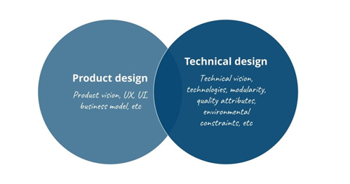
When talking about software design in this blog post, we are not referring to user experience design, user interface design or any of the other parts that make up the product design. We are talking about the technical software design; modularity, dependencies, technology choices and so on.

This is one of the main benefits of agile software development, that we’re not spending months and months up front, designing a system from end to end, creating massive amounts of documentation, without being able to test it with customers or seeing how the design choices work out in real life. By starting sooner, shipping early and often - and failing fast - the product can be tuned into what the customers actually need in a shorter period of time.
It’s always tempting to just start coding with the belief that our mentally devised solution will do the job and that by a few hastily drawn sketches on a whiteboard - communicated through a far from ideal video conferencing feed - manages to consolidate the entire team’s understanding of what we’re making. These whiteboard drawings are often captured with a cell phone camera and sometimes put on the wiki as “the documentation” and, maybe more often, never stored anywhere. When on-boarding a new team member, the design needs to be taught by someone who has a sufficient overview. Since the original drawing is not readily available, a new sketch is drawn during the on-boarding session - ending up as yet another drawing on the new team member’s phone. This new drawing is most likely not the same as the initial drawing and both drawings might not even depict what’s actually been created.
Just enough design and documentation
Agile product development is all about having an idea about what the product needs to be. The product team creates an initial implementation which is given to pilot customers. The pilot customers give feedback to the product team who will incrementally improve the product. This way, the development is controlled through a feedback loop which ensures the final product is actually what the customers need and is willing to pay for, not what we managed to capture in an upfront requirement capture process.

So, doing small, inexpensive changes from iteration to iteration brings us closer and closer to the ideal result, converging on a profitable product.
This technique can generally not be applied to technical software design.
Technical software design is about making architectural choices. These choices can be defined as the ones which are expensive to change, choices which typically requires lots of rework if altered. This can include technology, scalability, interoperability, performance, security, privacy and so on.
For example, for systems designed to be integrated - like how we plan our products and our business core systems will be integrated, comprising a fully digital customer journey - interoperability is key. If the conceptual data model were to change, the amount of rework needed would be tremendous. Or, even worse, if the upfront design work is skipped all together and the product teams compensate the lack of a common data model by shoehorning data into the least worst interpretation, huge problems will arise.
Another example of an expensive change could be changing from a monolithic to a distributed design. Doing the first iteration as a monolith and the second as an event based distributed set of services for instance requires a complete rewrite, not just incremental changes.
There’s a tremendous amount of choices we do all day, every day when creating software. Some of the choices are trivial, some are hard, some are cheap to change and some are expensive to change. We have to do enough upfront design to try to minimize the number of costly technical choices we do which have to be remade after they’ve been implemented.
Ok, I’m convinced - let’s start designing
There are a number of factors we have to take into account when designing. This is a study of its own and I’m not going to cover that in great detail here. But, as I see it, it’s made up of three main ingredients:
- Having a good understanding of both the functional and non-functional requirements
- A system context drawing (how my system fits into the landscape as a whole) and a system container drawing (the main parts of my system)
- A conceptual data model
Requirements
Requirements make up what our system needs to be. What functionality will be provided to the customer? What environmental constraints are there? How about scalability, security and interoperability? Are there any technological drivers or limitations in place (for example what are the competencies of the team)? What is the performance demand? And SLA?
All these questions (and more) make out the functional and non-functional requirements. Some can impose choices which are easily remade and some will be hard and costly to change. Therefore, having a clear view of the requirements and letting these drive the design, making architectural choices (again, the choices which are expensive to change) before starting implementation is key to success.
This isn’t to say we’re not allowed to change requirements after the implementation has started, but it’s about emphasizing the importance of capturing the requirements we have and letting these drive the design.
Design drawings
Actual drawing of software systems take many forms. Boxes, lines and arrows make up a large part. Throw in a stick man, a database and maybe some coloring and we’ve covered the majority.
But few drawings have the ability to be understood by new team members, or old members revisiting an old project, without an explanatory narrative. This narrative is seldom captured, and it’s up to the reader to interpret the drawing, or, if they’re lucky, have someone who still remember explain it to them.
C4 modeling
In Simployer we have decided to use the C4 model to design and document our software systems. This model is really effective in capturing the important parts of a technical design and at the same time giving the reader a comprehensible way of understanding the drawing without causing information overload.
Please go ahead and watch the introduction video on YouTube if you’re not already familiar with it:
Example
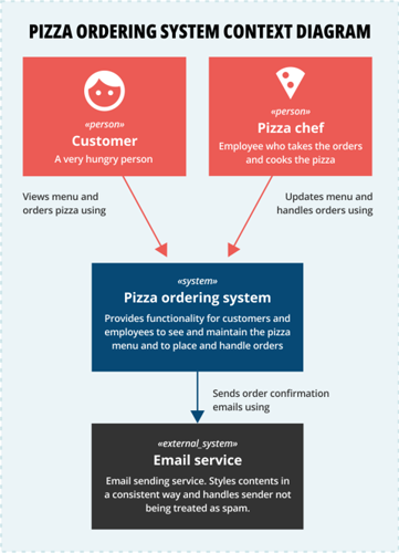
As an example of a system context diagram, imagine we’re making a system for ordering pizzas at a pizza restaurant. The system context is as follows:

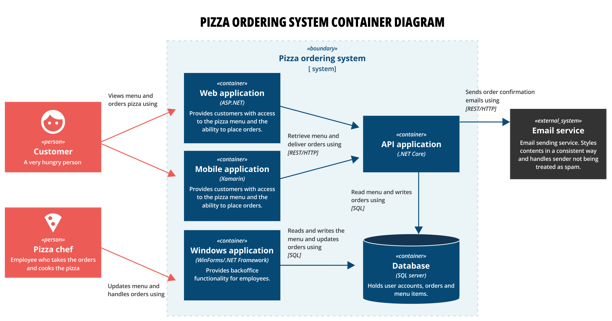
And the main parts of our pizza ordering system is this:

Notice how, even without giving an explanation of the drawings, the reader can understand how our new system fits into the whole and which parts it’s made up of.
Design drawings are a central tool for software teams to align around and to use as basis for design discussions. The design drawings also documenting what’s been made and will help future development teams in making conscious design decisions since inter- and intra-system dependencies now are visible, captured and maintained.
Conceptual data model
Where the system context drawing above shows what dependencies we have, which other systems our solution is talking to, the conceptual data model tells us what the systems are talking about.
The system context drawing tells us who is talking together, while the conceptual data model tells us what they’re talking about.
Hence, having a well defined conceptual data model is key in designing APIs, event contracts, bounded contexts, responsibilities and so on.
TL;DR
By actually doing a bit of technical software design work before starting implementation, we can create our solutions faster and cheaper with the added benefit of documentation being produced along the way.

